This documentation is for seting up an Attiny microprocessor for LED and a speaker.
This process is more complecated than the process in Electronics 1.1 but if you follow the
documentation you should do just fine.
For this project you will need a Speaker, Crocodile clips, resistor, wire, bread-board,
an Attiny, Arduino board, Program Arduino and Soldering space.
So, let's have some fun!
First of all you will need to download the Arduino Software.
You can download it from this link for free Download
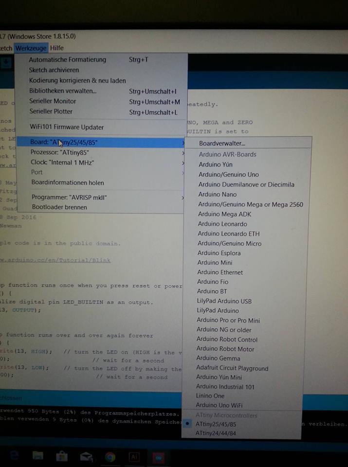
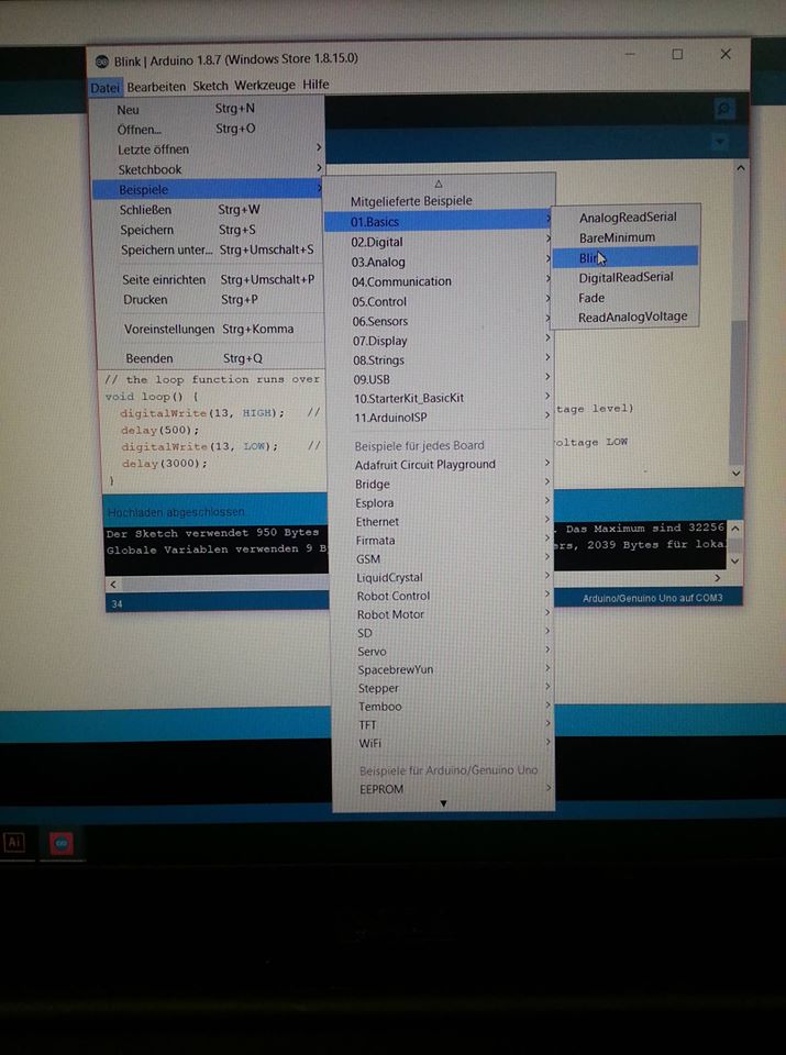
After you are done with the installation you need to set up your first sketch as it
is shown on the photo. (in English: File-> Examples-> 01.Basics-> Blink)
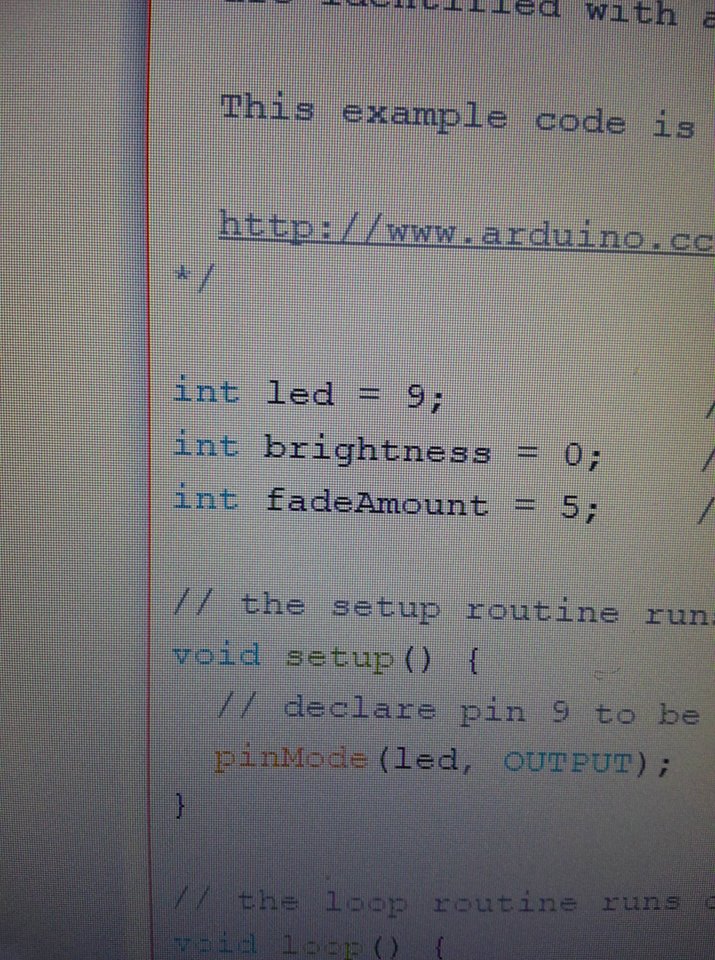
When you open the Blink sketch you will notice that the code is already there.
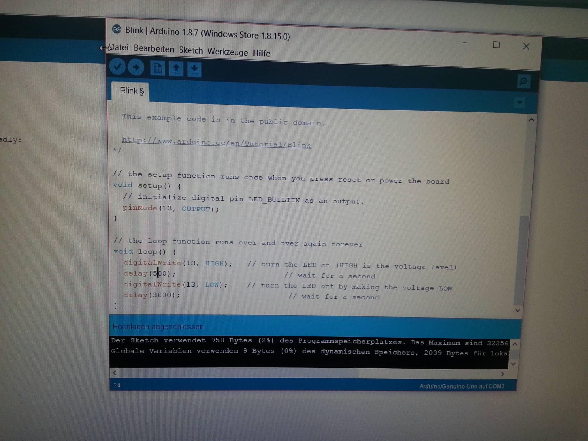
In the code that apears in the Blink sketch, there is one line indicating
the OUTPUT pin called pinMODE. There you should put the the number
of the pin (Arduino board pin) in which the + from the LED will go.
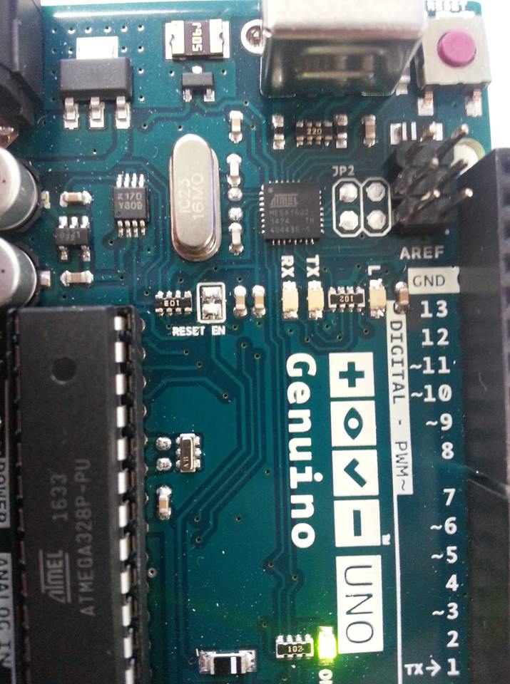
On the Arduino Board you can see the pin numbers. GND always indicates
the minus. So to attach and LED there it is logical to choose the nearby pin
for the +. In the photo shown above the pin chosen is number 13 as it is
exactly next to the GND one. In the Arduino program then we put OUTPUT pinmode 13.
After the set up is finished for our try out we can press in the up left corner
Prove ( to scan for any mistakes) and then after the scan connect the USB from
the Arduino to the PC and press Upload. Then if everything is correct the LED
should behave in the way we have programmed it to.
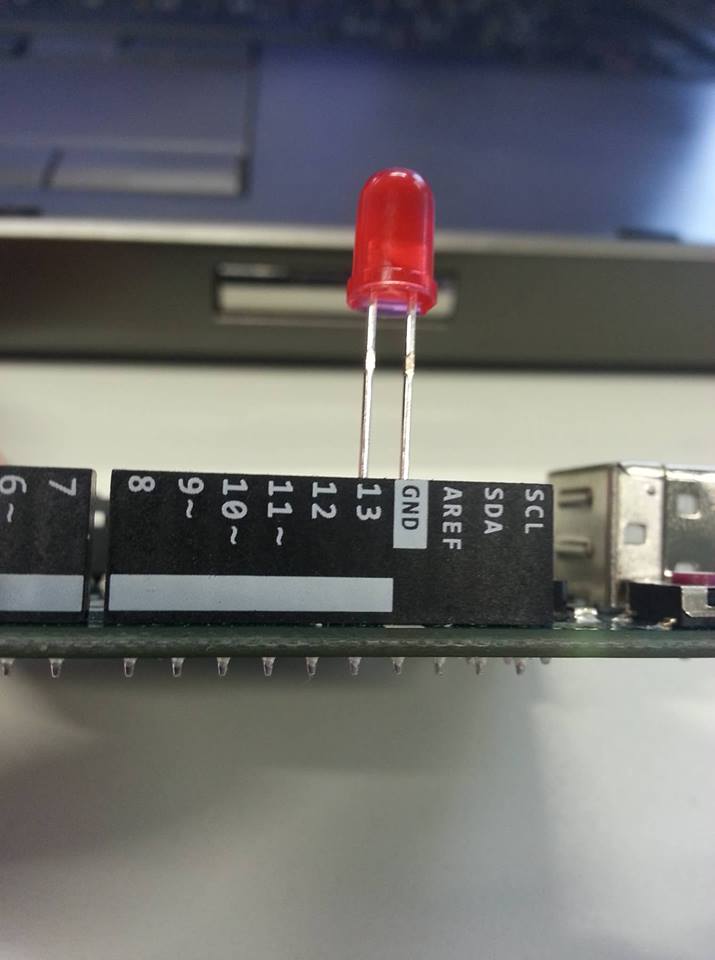
This is just an example of how I have positioned the LED.
The sketch Blink if obviously for making the LED blink (wow.. captain obvious! :D )
In the lower part of the code after the second commentar ( commentar indication // )
you will find the settings for the blinking qualities. After Digitalwrite
in the brackets you should put again the pin of the LED. The next line says
"delay": in there you can put a number and experiment with the delay of the blink
and different time values between each blink.
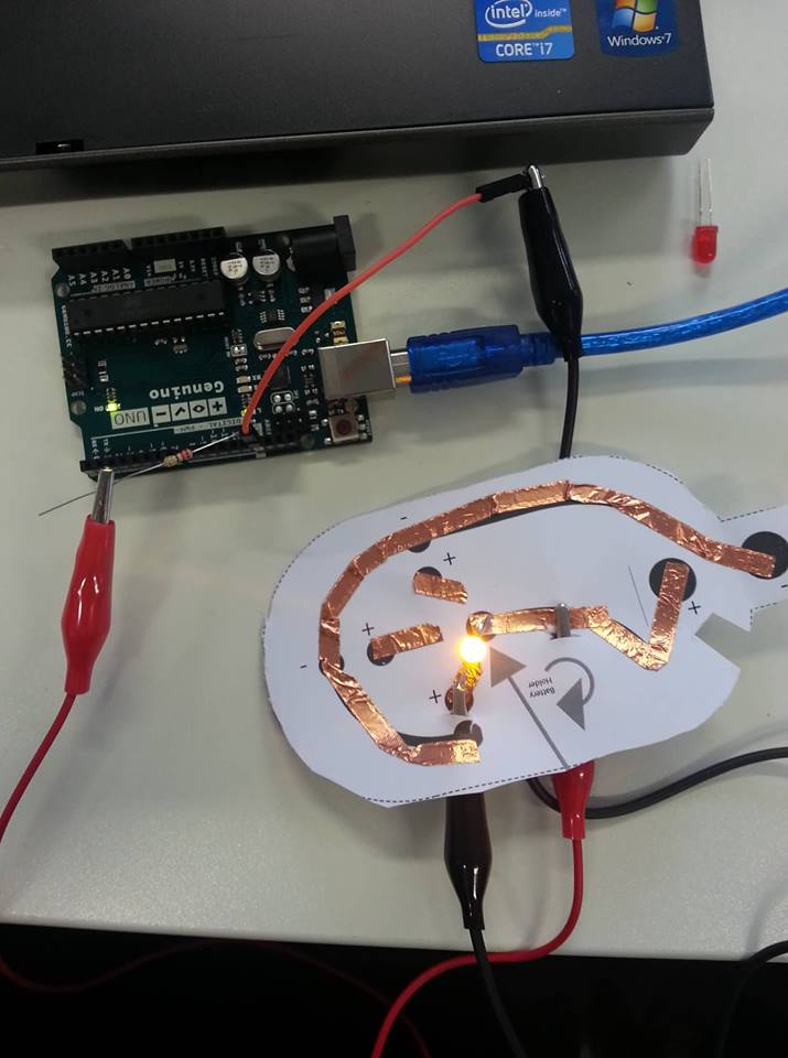
Now, because the Arduino board has always 5 V output we want to use a resistor for
our LED in case that it needs less than 5V. The resistor will come in the pin of
the input (13). Than to connect it with the LED, from the electronic circuit we have
created, we will use crocodile clips. It all needs to be connected in order the
electricity to flow. In the GND pin we put some of the additional wire and we
attach to it another crocodile clip. The crocodile clip connected with pin 13
goes to the + on the electronic circuit. The crocodile clip connected to the GND
goes to the - of the electronic circuit.
This is how we establish a connection between our Arduino board and the LED circuit.
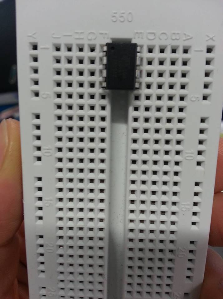
The bread Board is a board with many "wholes" in it. We use it to program the Attiny.
We have to put the Attiny in the middle of the board and press it good, because the
bottom of the board is conductive (this is how we comunicate between the Arduino board
and the Attiny). You can see rolls of wholes for each of the Attiny's legs. These pins
are connected. For example, the roll of pins on the bread board connected to each foot
is responsable (connected) for this Attiny pin number (foot).
goes to the + on the electronic circuit. The crocodile clip connected to the GND
goes to the - of the electronic circuit.
This is how we establish a connection between our Arduino board and the LED circuit.
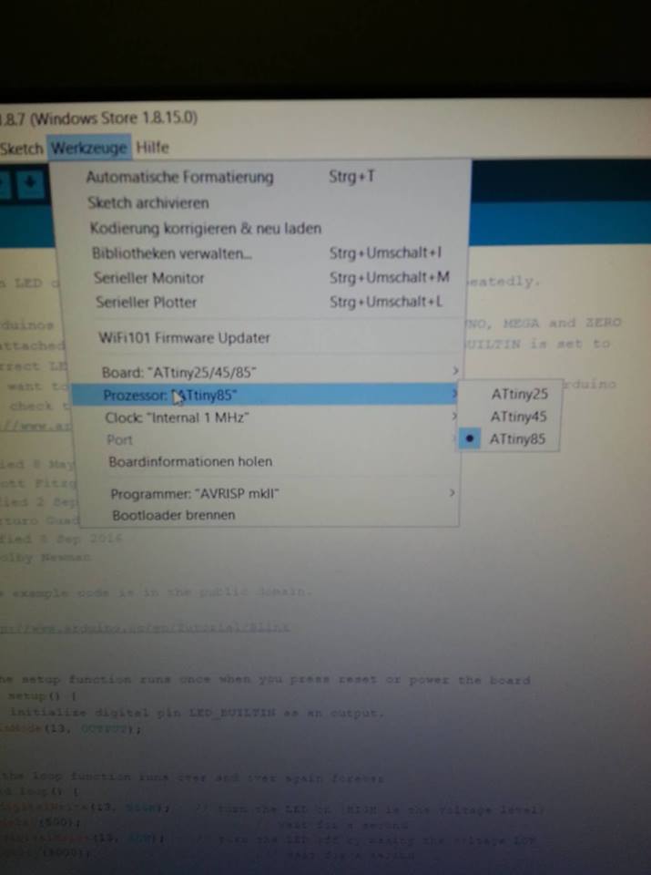
Because of including the speaker we changed the pinMODE from 13 to 9.
We have to always check for those to be the same in order to program the Attiny successfully.
Normally, these setting should not change but it is possible for them to restart.
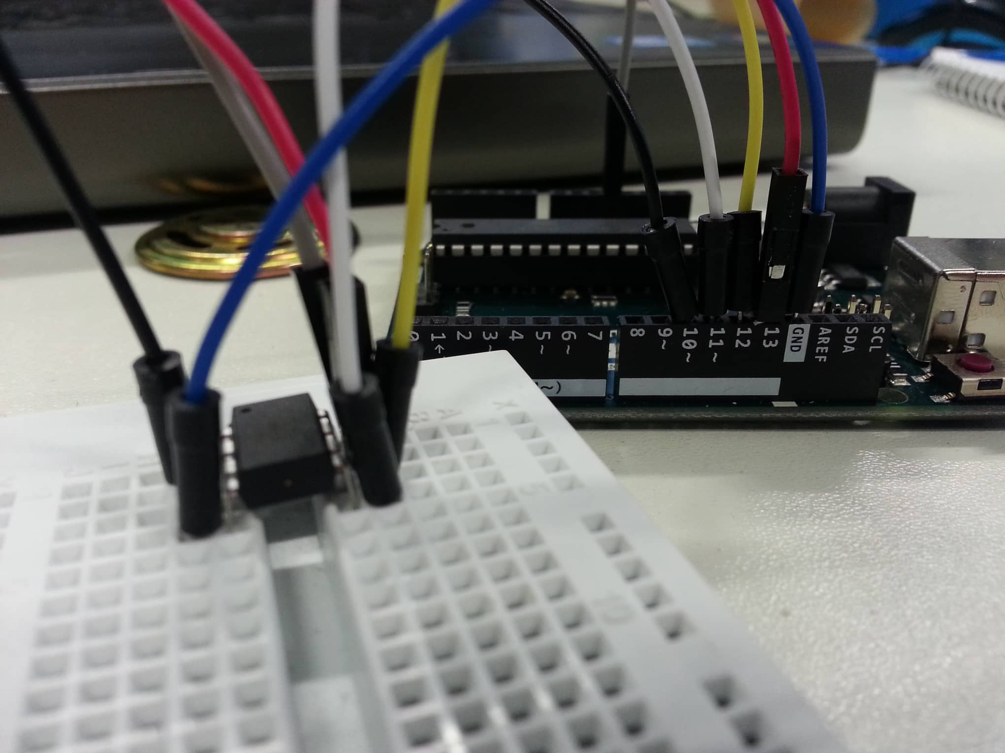
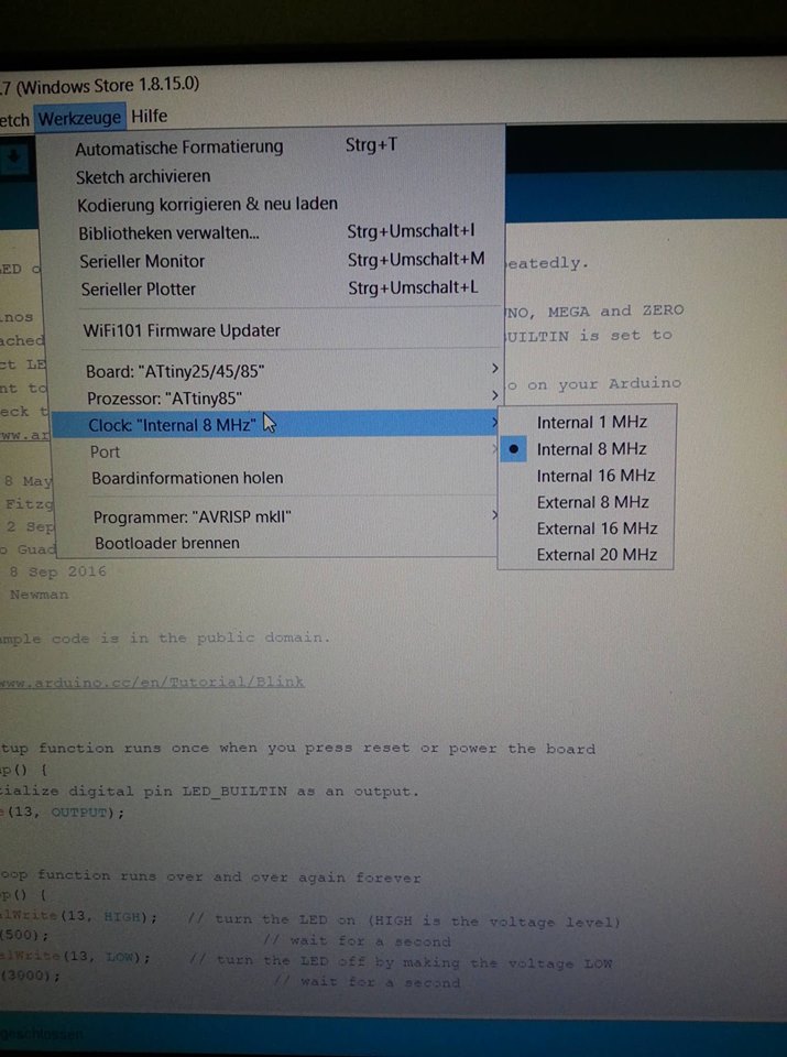
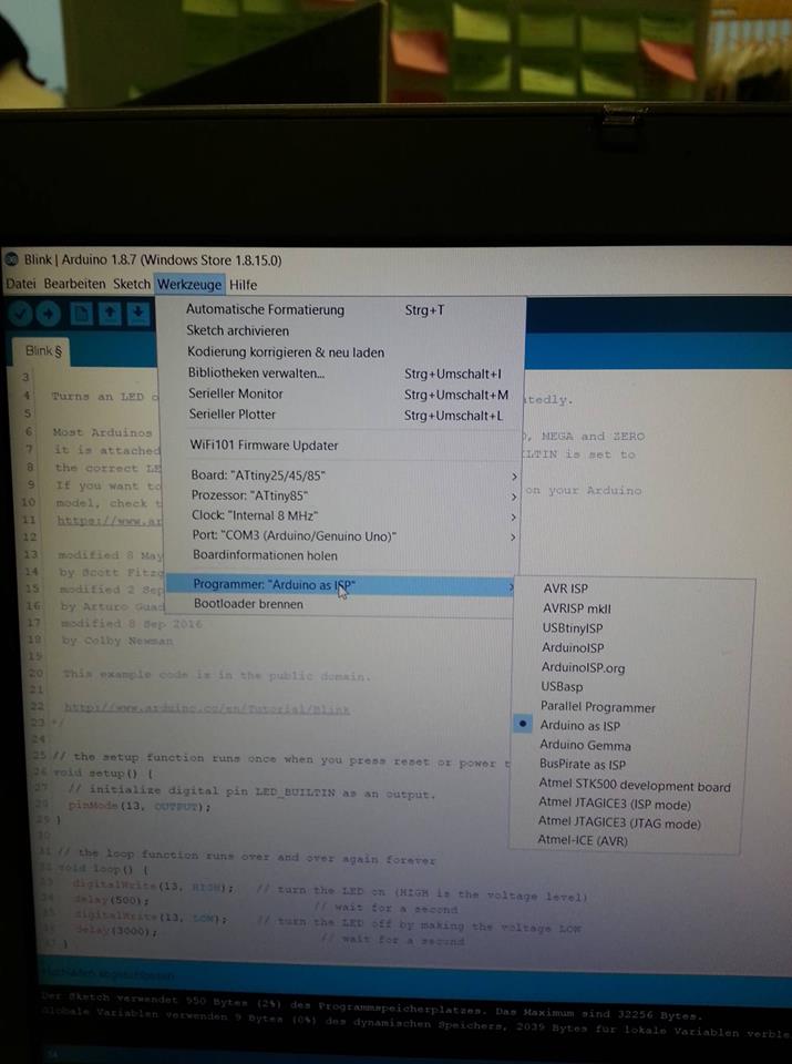
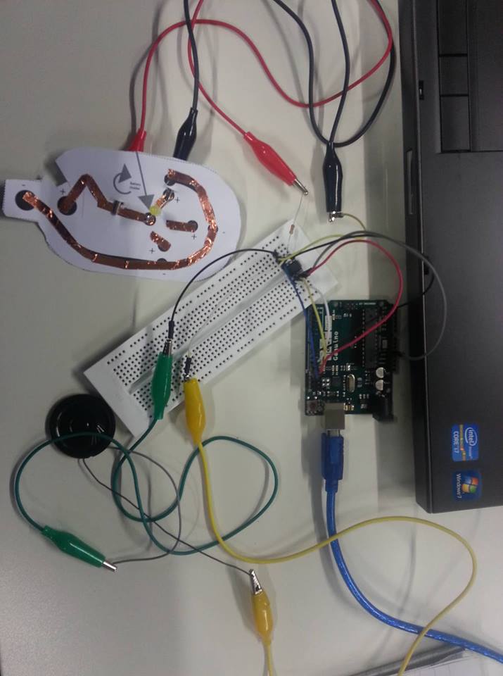
To asign settings to each leg of the Attiny we have to connect everythings we worked with
until now: Arduino Program + Arduino Board + Bread Board (Attiny)
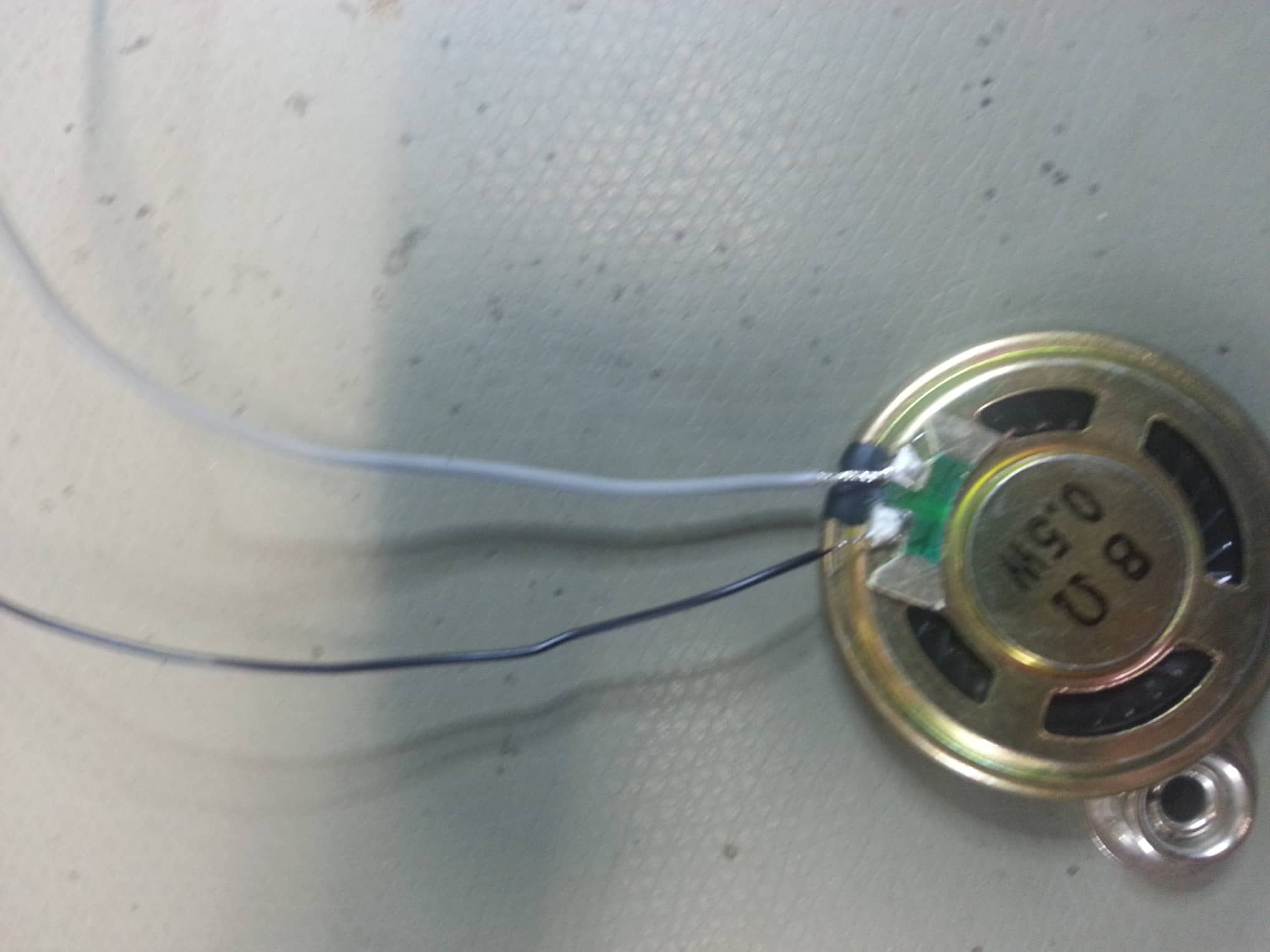
Normally, when you buy speakers online they come without the connecting wires.
If this is the case with your speaker then you have to solder some wires to the speaker.
For the sake of comfort, you can choose two different colors wire, to make the difference
easier.
The speaker only has + and - . So to connect and program it too, you have to connect
it to the Bread Board too using crocodile clips.
The speaker only has + and - . So to connect and program it too, you have to connect
it to the Bread Board too using crocodile clips.
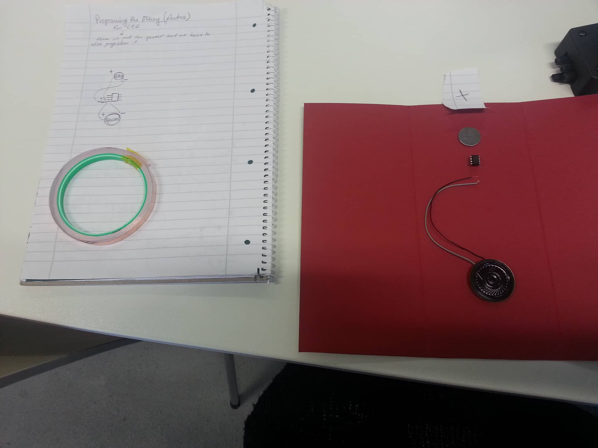
Based on my personal opinion, I decided to make two separate cards: one with LED and
one with a Speaker. So the following part of this documentation will focus on the
Speaker only.
So, I had to create an electrical circuit connecting the speaker with a battery
including a switch button as well. Of course all of these connected to the Attiny.
It is important to keep in mind that the cupper tape for each leg of the Attiny should
not have any points of touching as this will disturb the conduction. Because of the size
of the Attiny the cupper tape should be very thin or just cut thinner.
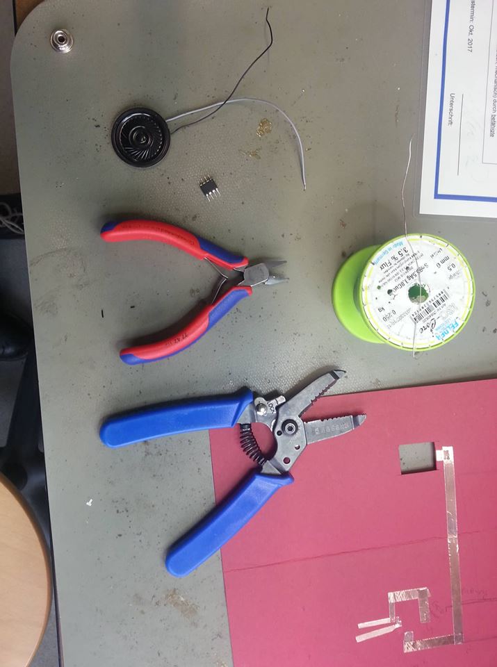
And after the scetch is ready too, then we can connect all the components by soldering.
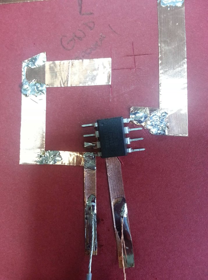
This is an example of my finished electronics for the inside of the christmas card.

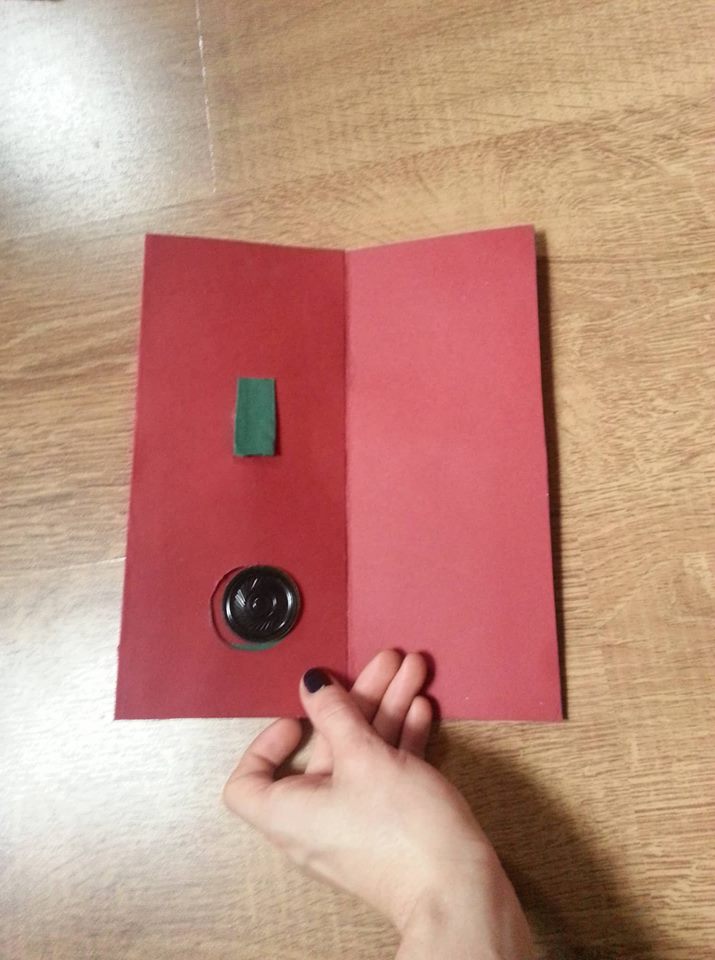
After the electronics of the project are done go for it and decorate it very nice!
Unfortunately, I did not make a video earlier and later on my speaker stopped
working properly, therefore I can upload only and image. The problem might be
the soldering of the Attiny or the speaker wires as they are very thin.
FabLab Kamp-Lintfort, Ms. Adriana Cabrera, Soft Prototyping
‹ ›